+86-411-85518978
zwa@zwa.cc

In simple terms, bearing clearance is the clearance (or interference) within a single bearing or a system composed of several bearings. Clearance can be divided into bearing axial clearance and bearing radial clearance, which depends on bearing type and measurement method.
For example, too much or too little water when cooking rice will affect the taste of rice. Similarly, too large or too small bearing clearance will reduce the working life of the bearing and even the stability of the entire equipment operation.
The method of clearance adjustment depends on the type of bearing, which can be generally divided into non-adjustable bearing and adjustable bearing.
Non-adjustable bearings refer to the bearings whose clearance is determined after leaving the factory. Deep groove ball bearings, self-aligning bearings and cylindrical bearings belong to this class.
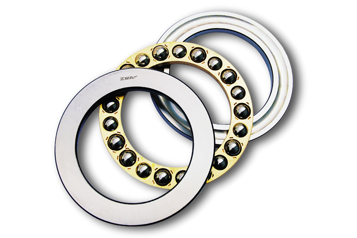
Adjustable bearings mean that the relative axial position of the bearing raceway can be moved to obtain the required clearance. Tapered bearings, angular contact ball bearings and some thrust bearings belong to this class.
For the non-adjustable bearings, the industry sets corresponding standard values (CN, C3, C4, etc.), and specific clearance ranges can also be customized. When the size of the shaft and bearing seat is known, the corresponding use level of the inner and outer rings is determined, and the clearance cannot be changed after installation. Since the use level is a range at the design stage, there is also a range at the final clearance, which is not applicable in applications requiring clearance accuracy.
Adjustable bearings solve this problem well. We can get a certain clearance value by changing the relative axial position of the raceway.
The choice of the optimal operating clearance is determined by the application conditions (load, speed, and design parameters) and the expected operating conditions (maximum life, best stiffness, low heat generation, ease of maintenance, etc.). However, in most applications, we cannot directly adjust the working clearance, so it requires us to calculate the appropriate post-installation clearance based on application analysis and experience.
The clearance of non-adjustable bearings is mainly affected by the fitting after installation, so the following mainly introduces the clearance adjustment method of adjustable tapered roller bearings, taking tapered roller bearings that have a wide speed range and can bear both axial and radial loads as an example.
1. Push-pull method
The push-pull method is generally used for positive clearance. The axial clearance between the bearing raceway and the rolling element can be measured. Apply a force to the shaft or bearing seat in one direction and set the dial gauge to zero for reference after pushing it to the bottom. Then apply a force in the opposite direction, and the rotational momentum of the pointer on the dial gauge after pushing it to the bottom is the clearance value. When measuring, the roller should be rotated by slow vibration to ensure that the roller is correctly positioned on the big flange of the inner ring.
2. Acro-SetTM method
The theoretical basis of Acro-Set is Hooke's law, which states that the shape variable of an object undergoing elastic deformation is proportional to the external force it is subjected to. Measure the spacer or spacer clearance to obtain the correct clearance under a certain mounting force. Read the correct gasket or spacer size directly from a chart created during prior testing.
This method is suitable for both positive clearance and pretightening, and operators need to be trained to create charts.
3. Torque-SetTM method
The principle of Torque Set is that, under preloading, the rotational torque growth of the bearing is a function of the bearing preloading force. The experimental results show that for a group of new roller bearings of the same type, under the condition of preloading force, the rotation moment of the bearing changes a little. Therefore, the rotational torque can be used to estimate the preload.
The principle of this method is to establish a conversion relationship between the rotational torque of the bearing and the preload, which needs to be obtained through testing. Then in the actual installation, the rotating torque can be measured to determine the thickness of the gasket.
4. Projecta-SetTM method
Projecta-Set projects or transforms the gasket or spacer thickness that cannot be directly measured to an easily measurable location, which can be achieved using a special gauge sleeve and spacer. Projecta-Set shows its advantages when the bearing removal and adjustment can be difficult and time-consuming if the inner and outer rings of the bearing are tightly fitted.
This method requires separate gauges for different types of ball bearings, and the cost is relatively high. When installed in large quantities, the average cost per installation is reasonable. It has been proved to be very effective especially in automation field.
5. Set-RightTM method
The Set-Right method uses a probabilistic approach and controls the dimensional tolerances of the relevant parts to ensure that 99.73% bearing clearance of all fitting assemblies is within acceptable limits. This is a mathematical prediction based on a combination of random variables, and the variables are bearing tolerances and tolerances of mounting components such as shafts and pedestals.
The bearing does not need to be installed and adjusted in this method, it can be clamped and assembled with simple components, so the mass installation is very convenient, but there will be a final clearance range (about 0.25mm). Whether the Set-Right method can be used in some applications needs to be decided at design stage. The Set-Right method has been used successfully for many years in both the industrial and automotive sectors.